Bending is a form of deformation, one of three primary processes in sheet metal fabrication; the other two being cutting and joining. Bending is done by holding the workpiece in position using clamps or dies and strategically applying force on an area of a workpiece. The force applied must exceed the yield strength of the material to cause the plastic deformation of the part. This process results in a v-shape, u-shape, or channel shape over an axis, creating a new part geometry. Bending changes the shape but the volume of the workpiece remains the same.
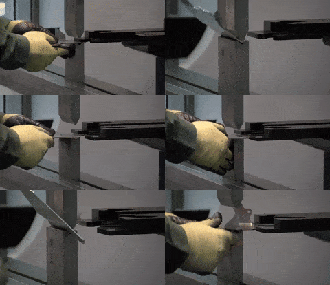
Types of Sheet Metal Bending
There are various methods for sheet metal bending. They are:
Air bending: This makes use of two dies; the upper die (also known as the punch) and the bottom die. The bottom die has a V-shaped opening. The punch forces the sheet metal into the bottom die. Air bending is not as precise as other methods.
Bottoming: In this method, the sheet metal is pressed onto the surface of the die by the punch. The metal then takes up the final angle, same as that of the die. For sheets about 3mm thick, the optimum width for the v-die opening is 6x the material thickness and about 12x the material thickness for 12mm thick sheets.
Coining: This is similar to air bending. However, the force used is usually 5 to 30 times the force for air bending. This gives a much higher precision.
Folding: Clamping beams are used to hold the longer side of the metal. The beam is free to rise and bend the sheet around a bend profile. Both negative and positive bend angles are possible.
Wiping: The longer side of the sheet is clamped, and a tool moves up and down, bending the metal around the bend profile. Wiping is relatively faster than folding but has a higher tendency of producing scratches or damaging the sheet.
Rotary bending: The top die is made of a cylinder that is free to rotate. The final shape for the bend is cut into it, and a matching bottom die. As the rolls contact the sheet, it rotates. The process bends the sheet.
Joggle bending: This is an offset bending. The two opposite bends are less than 90 degrees each. A neutral web separates the opposite bends.
Design Tips for Bending
To ensure a hitch-free bend and to avoid deformation, the following 10 tips are vital when designing.
1. Part thickness
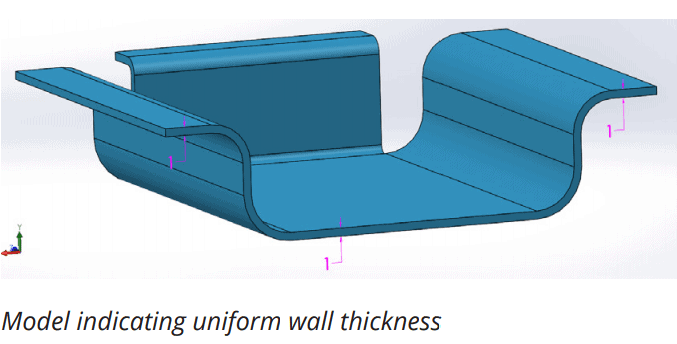
Parts must have a uniform wall thickness throughout. Xometry Europe is capable of manufacturing bent sheet metal parts up to 6.35mm in thickness, but this tolerance mainly depends on the geometry
2. Hole and slot clearance
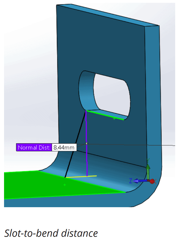
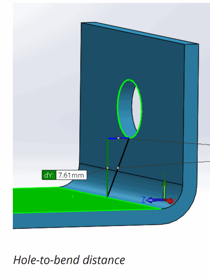
The distance of holes from the bend should be at least 2.5x the material thickness. Slots require more clearance. Slots should be placed at a distance of at least 4x the material thickness from the bend edges. This is because holes and slots are likely to deform when placed near a bend. Also, to avoid a bulging effect, place these features at a distance of at least 2x the material thickness from part edges.
3. Bend radius
The radius of bends must be a minimum of 1x the material thickness to prevent parts from fracturing or distorting. Also, the Bend radius should be kept consistent to minimize cost.
All bends in the same plane should be designed in one direction to prevent part reorientation. This saves both money and time.
Large, thick parts should not have small bends due to the high tendency to become inaccurate. As a rule of thumb, the inside bend radius should at least equal to the material thickness.
4. Curls
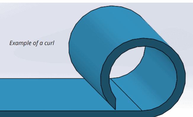
The outside radius of curls must be at least twice the material thickness.
In addition, the distance of holes from curls should be at least equal to the curl radius plus the material thickness. Other bends should be placed away from the curl at a distance of at least 6x the material thickness plus the curl radius.
5. Clearance for countersink
Countersinks on sheet metal parts are usually produced with hand tools. They must not be deeper than 0.6x the material thickness. This means that the maximum depth of a countersink in a 10 mm thick material should be 6 mm.
Furthermore, countersinks must have a minimum distance of 3x the material thickness from a bend, 4x from an edge, and 8x from each other.
6. Hems
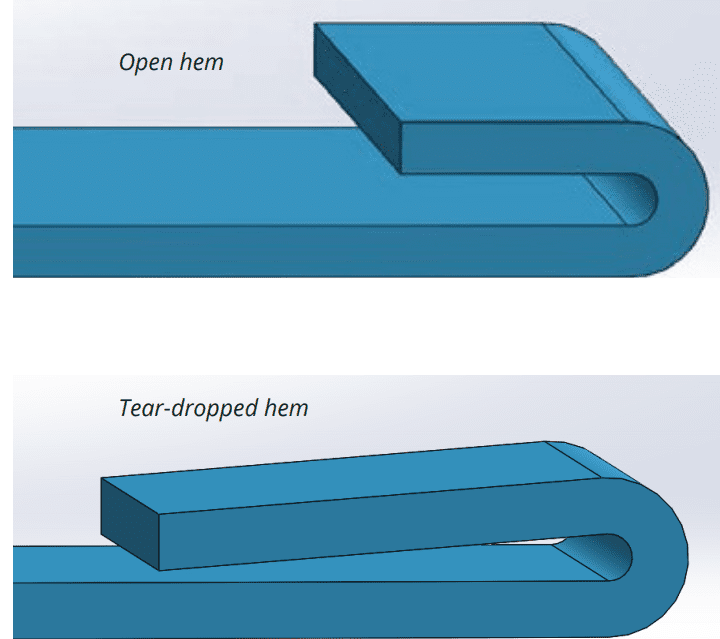
Hems are folds created at the edge of parts to create a safe, rounded edge. There are three hem designs with different design rules.
For open hems, the minimum inside diameter should be at least equal to the material thickness, as larger diameters will cause loss of circularity. To ensure a perfect bend, the return length should be 4x the material thickness.
Teardrop hems should also have a minimum inside diameter that is equal to the material thickness. The opening should be a minimum of ¼x the material thickness, while the run length should be at least 4x the material thickness following the radius.
7. Chamfered sides
Chamfers on flanges must leave enough room for bends to avoid deformed parts.
8. Bends next to each other
Successive bends should be avoided except when absolutely necessary. A common problem for successive bends is the difficulty to fit the already bent parts on the die. However, when unavoidable, the intermediate part should be longer than the flanges.
9. Clearance for notches and tabs
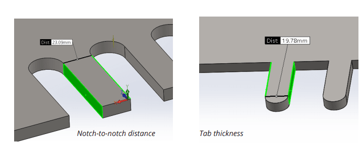
The notch to bend distance should be at least 3x the material thickness plus the radius of the bend. Tabs, on the other hand, must be 1 mm or the material thickness away from each other, whichever value is greatest.
10. Relief cuts
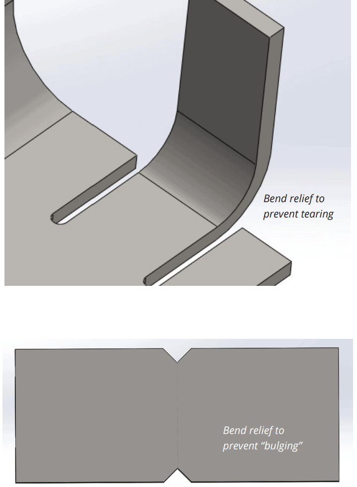
Relief cuts are essential in avoiding bulging and tearing at bends. The width of the relief cuts should at least be equal to the material thickness, and the length should be longer than the radius of the bend.
Calculating Required Bending Force
Different factors are involved in creating the right bend in a workpiece. These include:
- Bending strength of the material
- Degree of bending
- Thickness of the workpiece
- Bend angle
- Internal radius
- Vee die opening
- Minimum internal edge
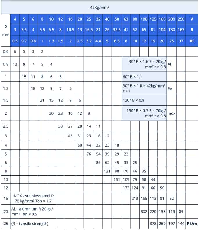
The chart below can be used to calculate the bending force required to V bend mild steel S235 of different thicknesses, in different shapes, at an angle of 90°. Mild steel S235 has a bending strength of 42 kg/mm². The variable parameters are as follows.
- S (mm) – Thickness of the workpiece
- V (mm) – Vee die opening
- B (mm) – Minimum internal edge
- Ri (mm) – Internal radius
Conclusion
At Xometry Europe, we offer high-precision, fast, and quality sheet metal bending and fabrication services for the creation of parts out of sheet metal such as aluminium, steel, copper alloys, and many others. Using automated bending techniques, we guarantee high precision and quality of ready parts.
We also carry out post-processing upon your request. To get an instant quote, upload your models on our instant quoting platform.